About Microseismic Monitoring & Interpretation
Overview
Micro-seismic Real-time Monitoring technology inside well is a key technology for the exploration and development of unconventional fields such as shale gas and tight oil and gas. Compared with ground microseismic real-time monitoring & real-time decision technology, monitoring is more closer inside well, more accurate and more clearly reflect the fracture length, fracture height, and real-time extension in the fracturing process, so that, technicians analyze and study the formation transformation more accurately, evaluate the fracturing effect in real-time, and guide the fracturing parameters efficiency. The adjustment of the plan reduces the period and cost of reservoir reform monitoring, it is one of the most accurate, timely and informative monitoring methods in the fracturing process.

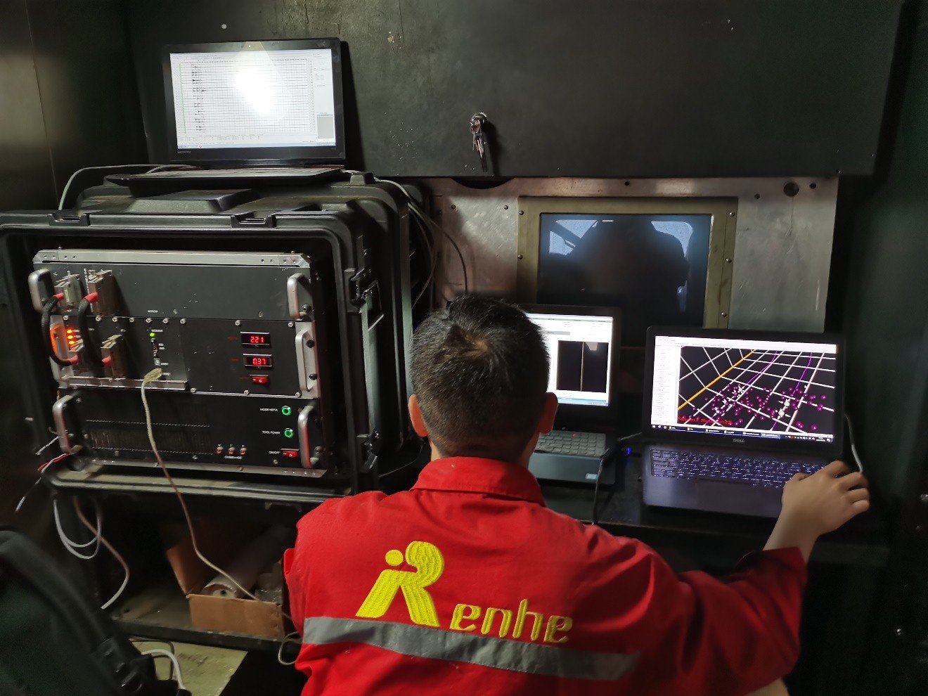
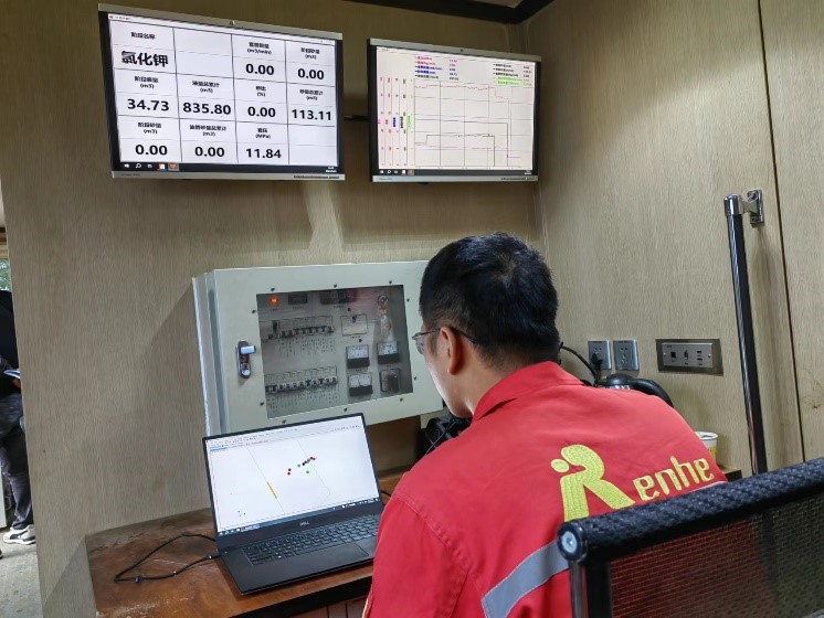
Real-time Wellsite Interpretation
Applications
Real-time monitoring: Check the fracturing effect, analyze the fracture morphology in real-time, adjust the fracturing parameters (such as pressure, sand volume, fracturing fluid, temporary ball plug, etc.), monitor the casing change, guide the fracturing construction in real-time, optimize the fracturing plan.
Fracturing evaluation: Provide fracture network geometry, comprehensive analysis by combined with well logging, rock geophysical parameters, seismic data and other information to evaluate the fracturing effect and estimate the available oil and gas Stimulated Reservoir Volume (SRV).
Development application: Provide fracture space shape and maximum main in-situ stress direction, etc. And provide important reference for the layout of oilfield development well patterns (horizontal well spacing, horizontal section length, fracturing classification and fracturing section length, etc.).
Tool Features
MultiVSP and MagnetVSP can work at 0.25 millisecond sampling rate with up to 12-level detectors, which make events to be located more accurate.
For long horizontal well fracturing, placing the geophones in a vertical well is often limited by the monitoring distance and cannot achieve monitoring all stages in treatment well, or sometimes a vertical monitoring well whose distance to the treatment well is suitable can not be found. At this time MagnetVSP can be conveyed by downhole tractor to the horizontal interval to complete monitoring all stages in treatment well.
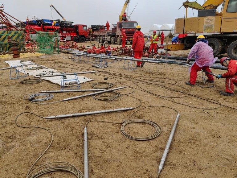
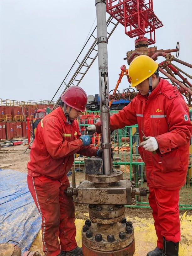
Case
The microseismic monitoring was performed in ShanXi province,the treatment well is a horizontal well where the reservoir is sandstone. The geophones were placed in horizonal interval of three different depth to achieve
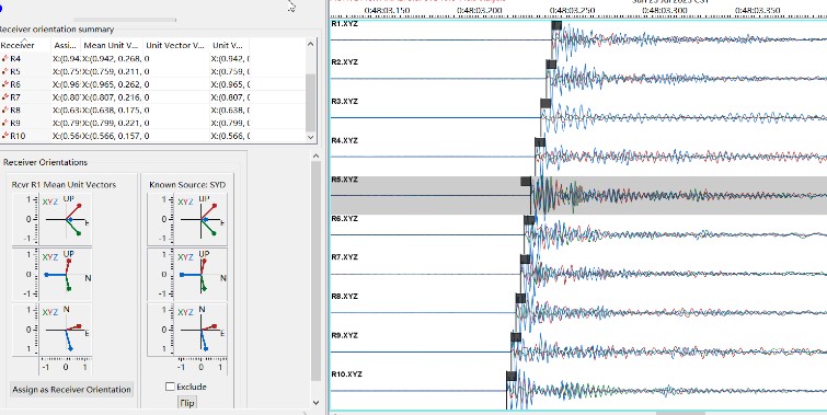
Oriented Signal
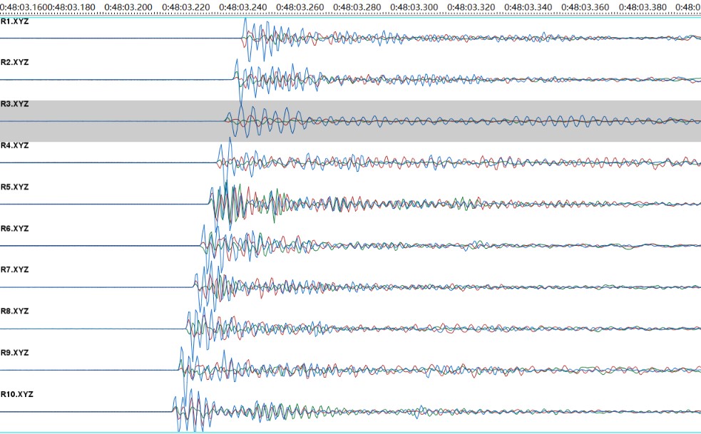
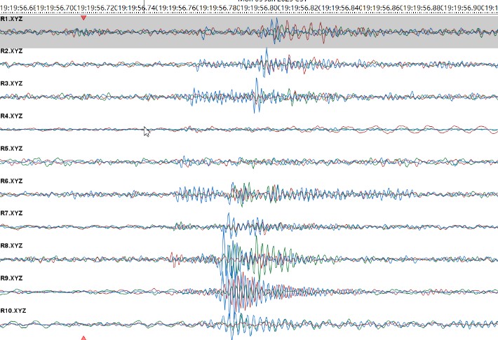
Event Signal
Perforation Shot Positioning Results (Interval 1)
Velocity model correction results (Interval 1)

Crack Orientation Analysis
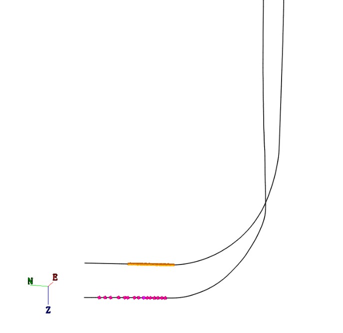
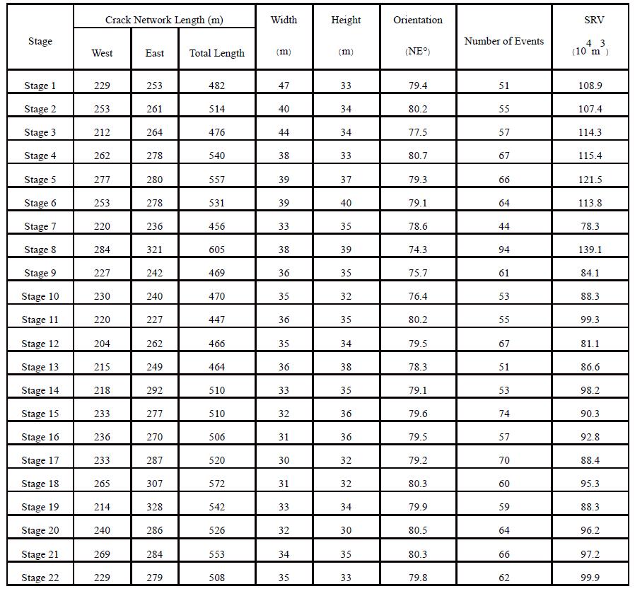
The microseismic monitoring results of the treatment well show that the fracture direction ranges from NE 74.3 ° to NE 80.7 °, with an average of 79 °. The fracture orientation is basically perpendicular to the well trajectory direction. Except for Stage 7, cracks in Stages 1-13 mainly develop above the perforation shots location, while cracks in Stage 14-22 develop relatively evenly on both sides of the perforation shots location.


Microseismic Monitoring Crack Morphology Table
Conclusion & Suggestions:
1. The microseismic monitoring results of treatment well show that the fracture direction ranges from NE 74.3 ° to NE 80.7 °, with an average of 79 °. The fracture orientation is basically perpendicular to the well trajectory direction, and the fracture height mainly develops above the perforation shots location.
2. According to the microseismic monitoring results, the average fracture width of the 1-22 stages of the treatment well is 36 meters, the average dessert length is 40 meters, and the average interval between Stages is 24 meters. The seam width is smaller than the interval between the stages, but the crack width basically corresponds to the dessert length, making the design more suitable.
3. The overall number of microseismic events during the carbon dioxide pre energy replenishment stage is relatively low (there are relatively more in the 16th, 17th, 21st, and 22nd segments), and a large number of microseismic events occur during the sand carrying fluid stage. However, from the perspective of crack morphology, cracks have already formed during the carbon dioxide stage.
4. From the analysis of the crack morphology before and after temporary blocking in each stage, it can be seen that the cracks have roughly formed before temporary blocking, and after temporary blocking, the cracks continue to extend along the original cracks without significant changes in the height of the crack network.
5. The amount of liquid entering each stage of the well is positively correlated with the SRV.
6. By comparing the half length of microseismic cracks with the design half length, it was found that the microseismic interpretation of the west crack is basically the same as the design crack half length, but the length of the east crack is greater than the design crack half length, with the most obvious after the Stage 12. It is recommended to slightly reduce the scale of fracturing construction in this area.
